Steel Shapes Area Calculator
Use the Steel Shapes Area Calculator – a powerful tool that simplifies these calculations, saving time and reducing errors.
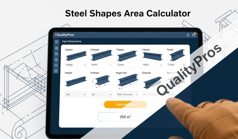
Structural Shape Area Calculator
Why Calculate Cross-Sectional Area in Steel Design? 🏗️
Cross-sectional area isn’t just a number – it’s the backbone of structural integrity:
- Strength and Stability: Area influences moment of inertia (I) and section modulus (S), key for bending and torsion resistance.
- Weight Estimation: Essential for logistics, crane capacity, and cost (e.g., reducing backlogs in fabrication registers by accurate planning).
- Material Optimization: Helps select efficient shapes, minimizing waste and aligning with sustainability goals in ISO 9001:2026.
- Compliance and Safety: Ensures designs meet codes like AS/NZS 3678 for Australian steel, preventing failures from underestimation.
In practice, QA/QC teams use these calculations during weld visual inspections or NDT to verify material specs, addressing PIP issues like non-standard documentation.
Common Steel Shapes and Their Area Formulas 📏
Steel comes in various profiles, each with unique formulas derived from geometry. Below are tables categorized by shape type, including descriptions, formulas, and example calculations. Formulas assume standard dimensions without fillets (for simplicity; advanced calculators adjust for them). Units are in mm² for area, with dimensions in mm.
Basic Shapes (Bars and Plates)
These are simple profiles used in fabrication and supports.
| Shape | Description | Formula | Example Calculation |
|---|---|---|---|
| Rectangular Bar/Plate | Flat rectangle, e.g., steel plates | A = width (b) × height (h) | b=100mm, h=50mm: A=5000 mm² |
| Square Bar | Equal-sided square | A = side (s)² | s=40mm: A=1600 mm² |
| Round Bar | Circular solid bar | A = π r² (r=radius) | r=20mm: A=π×400≈1256.64 mm² |
Structural Shapes (Beams and Channels)
Used in load-bearing applications like beams and frames.
| Shape | Description | Formula | Example Calculation |
|---|---|---|---|
| I-Beam (Wide Flange) | H-shaped with flanges and web | A = 2×(flange width (b_f) × flange thickness (t_f)) + (web height (h_w) × web thickness (t_w)) | b_f=200mm, t_f=10mm, h_w=300mm, t_w=8mm: A=2×(200×10) + (300×8)=6400 mm² |
| Channel (C-Shape) | U-shaped with flanges and web | A = 2×(flange width (b_f) × flange thickness (t_f)) + (web height (h_w) × web thickness (t_w)) | b_f=100mm, t_f=8mm, h_w=200mm, t_w=6mm: A=2×(100×8) + (200×6)=2800 mm² |
| Tee (T-Shape) | T-shaped bar | A = (flange width (b_f) × flange thickness (t_f)) + (stem height (h_s) × stem thickness (t_s)) | b_f=150mm, t_f=10mm, h_s=100mm, t_s=8mm: A=(150×10) + (100×8)=2300 mm² |
Angular and Hollow Shapes
Ideal for frames, bracing, and tubing.
| Shape | Description | Formula | Example Calculation |
|---|---|---|---|
| Angle (L-Shape) | Equal or unequal legs | A = (leg1 length (a) × thickness (t)) + (leg2 length (b) × t) – t² | a=100mm, b=100mm, t=10mm: A=(100×10) + (100×10) – 100=1900 mm² |
| HSS Square (Hollow) | Square tube | A = side_outer² – side_inner² | Outer=100mm, inner=80mm (wall=10mm): A=10000 – 6400=3600 mm² |
| HSS Rectangular | Rectangular tube | A = (width_outer × height_outer) – (width_inner × height_inner) | Width_outer=150mm, height_outer=100mm, wall=10mm: A=15000 – 130×80=4600 mm² |
| Pipe (Round HSS) | Circular tube | A = π (R_outer² – R_inner²) | R_outer=50mm, R_inner=40mm: A=π(2500-1600)=π×900≈2827.43 mm² |