CJP vs. PJP Welds
Welding is the backbone of industries like construction, shipbuilding, and energy, where the choice of weld type can make or break a structure’s integrity. Two fundamental weld types—Complete Joint Penetration (CJP) and Partial Joint Penetration (PJP)—play critical roles in determining strength, cost, and project feasibility. Understanding their meanings, symbols, differences, and applications is essential for engineers, welders, and inspectors to ensure safety and compliance with standards like AWS D1.1, ASME BPVC, AS/NZS 1554.1, AS/ NZS 5131 and CSA W59.
In this comprehensive blog post, we’ll explore CJP and PJP welds in detail, covering definitions, weld symbols, calculations, pros and cons, practical examples, and more, while addressing key search terms like “CJP weld meaning,” “PJP weld symbol,” and “CJP vs PJP welding” to provide a clear, accurate, and actionable guide.
What Are CJP and PJP Welds?
Complete Joint Penetration (CJP) Weld
A CJP weld achieves full penetration through the thickness of the joined materials, ensuring the weld metal fuses completely from one side of the joint to the other. This results in a weld with strength equal to or greater than the base metal, making it ideal for critical, high-load applications.
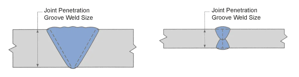
- Key Feature: Weld penetrates the entire joint thickness, often requiring backing bars or back-gouging to ensure root quality.
- Standards Reference: AWS D1.1:2020 Clause 2.4.2.1 defines CJP as a groove weld with complete fusion; ASME BPVC Section IX:2023 QW-410 specifies qualification requirements.
Partial Joint Penetration (PJP) Weld
A PJP weld penetrates only part of the joint thickness, leaving an unfused portion. The weld’s strength depends on the effective throat (penetrated depth), making it suitable for less critical applications or where full strength isn’t required.
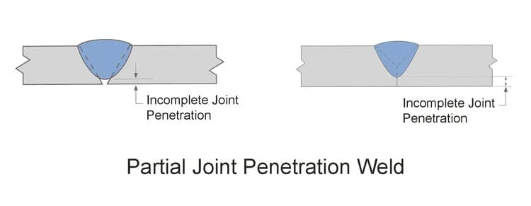
- Key Feature: Specified penetration depth is less than the joint thickness, controlled by weld size or throat.
- Standards Reference: ISO 5817:2023 Clause 5.2 allows PJP for quality levels B, C, D; AS/NZS 1554.1:2014 Clause 4.7.3 defines PJP throat size.
Why Understanding CJP vs. PJP Matters
Choosing between CJP and PJP impacts structural performance, cost, and fabrication time. A CJP weld in a bridge girder ensures maximum strength under dynamic loads, while a PJP weld in a non-critical bracket saves time and material. Misapplying these welds—using PJP where CJP is needed—can lead to failures, while overusing CJP increases costs unnecessarily. Standards like AWS D1.1, ASME, and EN 1011-2 guide these decisions, ensuring welds meet design intent.

Weld Symbols for CJP and PJP
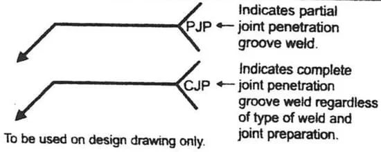
Weld symbols, per AWS A2.4:2020 and ISO 2553:2019, communicate weld type, size, and preparation on engineering drawings. Here’s how CJP and PJP are represented:
CJP Weld Symbol
- Groove Weld: Typically a square, V, U, or bevel groove with a “CJP” notation in the tail or no weld size specified (implying full penetration).
- Characteristics:
- No weld size in parentheses (e.g., no “(6)” for 6 mm throat).
- May include “backing” or “back-gouging” notes.
- Flush or reinforced weld face.
- Example Symbol (AWS A2.4):
- Square groove, double-sided: [Square symbol with “CJP” in tail]
- Single V-groove with backing: [V symbol, backing bar indicated, “CJP” note]
PJP Weld Symbol
- Groove or Fillet Weld: Specifies weld size (effective throat or leg length) in parentheses.
- Characteristics:
- Weld size (e.g., “(8)” for 8 mm throat) shown next to the symbol.
- Groove type (e.g., bevel, J) indicates partial penetration.
- May include angle or root opening details.
- Example Symbol (ISO 2553):
- Single bevel groove: [Bevel symbol with “(6)” for 6 mm throat]
- Fillet weld: [Triangle symbol with “z8” for 8 mm leg length]
Symbol Comparison Table
| Aspect | CJP Weld Symbol | PJP Weld Symbol |
|---|---|---|
| Notation | “CJP” in tail or no size specified | Weld size in parentheses (e.g., “(5)”) |
| Groove Type | Square, V, U, Bevel | Bevel, J, Flare-bevel, Fillet |
| Penetration | Full thickness | Partial, specified depth |
| Example (AWS) | [V-groove, “CJP”] | [Bevel, “(8)”] |
| Example (ISO) | [Square, “CJP”] | [J-groove, “a5” for 5 mm throat] |
Differences Between CJP and PJP Welds
The choice between CJP and PJP hinges on strength, cost, and application. Here’s a detailed comparison:
| Parameter | CJP Weld | PJP Weld |
|---|---|---|
| Penetration | Complete, through entire joint thickness | Partial, specified depth less than thickness |
| Strength | Matches or exceeds base metal strength | Limited by effective throat; lower than base metal |
| Weld Volume | Higher; requires more filler metal | Lower; less filler needed |
| Preparation | Complex (e.g., double V-groove, back-gouging) | Simpler (e.g., single bevel, no backing) |
| Cost | Higher due to material, labor, and time | Lower; faster and less material-intensive |
| Inspection | Rigorous (UT, RT for full penetration) | Less stringent (visual, MT for surface) |
| Applications | Critical structures (bridges, pressure vessels) | Non-critical joints (brackets, secondary members) |
| Standards | AWS D1.1, AS/ NZS 1554.1, AS/NZS 5131, CSA 59, EN 15085-2 | AWS D1.1, AS/ NZS 1554.1, AS/NZS 5131, CSA 59, EN 15085-2 |
| Weld Imperfections | Lack of fusion critical; stricter tolerances | Incomplete penetration acceptable if within spec |
Pros and Cons of CJP and PJP Welds
CJP Welds
| Pros | Cons |
|---|---|
| Maximum strength; matches base metal | Higher cost (material, labor) |
| Ideal for dynamic or cyclic loads | Complex preparation (grooves, backing) |
| No unfused areas; high reliability | Rigorous inspection (UT, RT) required |
| Preferred for critical applications | Slower welding process |
PJP Welds
| Pros | Cons |
|---|---|
| Cost-effective; less filler and time | Limited strength; depends on throat |
| Simpler preparation and welding | Not suitable for high loads or fatigue |
| Flexible for non-critical joints | Risk of incomplete penetration defects |
| Easier inspection (visual, MT) | May require thicker members to compensate |
Practical Applications and Examples
Example 1: CJP Weld in a Bridge Girder (AWS D1.1)
- Scenario: Welding a 25 mm thick ASTM A572 Gr. 50 girder flange to a web for a highway bridge.
- Weld Type: CJP double V-groove, SMAW with E8018-C3.
- Symbol: [Double V, “CJP”, back-gouging note]
- Calculation:
- Joint thickness: 25 mm; full penetration.
- Strength: Matches 345 MPa yield of base metal.
- Weld length: 2 m, capacity ≈ 10,350 kN (0.75 × 345 × 25 × 2000).
- Application: Ensures fatigue resistance under traffic loads.
- Inspection: Ultrasonic testing (UT) confirms no lack of fusion.
- Outcome: Weld meets AWS D1.1 Clause 6; bridge passes safety checks.
Example 2: PJP Weld in a Storage Tank (ASME BPVC IX)
- Scenario: Attaching a 12 mm thick SA-516 Gr. 70 nozzle to a tank shell.
- Weld Type: PJP single bevel groove, 6 mm throat, GTAW with ER70S-2.
- Symbol: [Bevel, “(6)” for throat]
- Calculation:
- Effective throat: 6 mm.
- Weld length: 300 mm.
- Strength: 0.75 × 290 × 6 × 300 / 1000 ≈ 391 kN.
- Application: Non-pressure boundary; sufficient for static load.
- Inspection: Visual and magnetic particle testing (MT); macro-etch for qualification.
- Outcome: Cost-effective weld meets ASME IX QW-452.3.
Example 3: PJP Fillet Weld in a Crane Bracket (AS/NZS 1554.1)
- Scenario: Welding a 10 mm thick A36 bracket to a column.
- Weld Type: PJP fillet weld, 7 mm leg length, FCAW with E71T-1.
- Symbol: [Triangle, “z7”]
- Calculation:
- Throat: ( 7 \times 0.707 \approx 4.95 \text{ mm} ).
- Length: 200 mm.
- Strength: 0.75 × 290 × 4.95 × 200 / 1000 ≈ 215 kN.
- Application: Secondary member; load < 200 kN.
- Inspection: Visual check with fillet gauge; meets ±1 mm tolerance.
- Outcome: Efficient weld satisfies AS/NZS 1554.1 Clause 4.7.3.
Practical Considerations
- CJP for Critical Joints: Use in seismic zones, pressure vessels, or heavy machinery where failure is catastrophic.
- PJP for Efficiency: Ideal for secondary connections, non-load-bearing members, or cost-sensitive projects.
- Inspection Needs: CJP requires NDT (UT, RT); PJP often passes with visual/MT, per ISO 5817.
- Material Thickness: CJP suits thicker plates (>10 mm); PJP viable for thinner sections.
- Welding Process: CJP often uses SAW or FCAW for efficiency; PJP flexible with SMAW, GMAW.
Common Pitfalls and Solutions
- Misreading Symbols: Verify “CJP” vs. “(size)” in drawings to avoid incorrect welds (AWS A2.4).
- Underestimating Loads: Ensure PJP throat meets design forces; use CJP for unknown fatigue (ASME IX).
- Poor Preparation: CJP needs precise groove angles (e.g., 60° V); PJP tolerates simpler bevels (ISO 2553).
- Inspection Oversights: Missing lack of fusion in CJP fails AWS D1.1 Clause 6; check PJP throat with gauges.
Summary Table: CJP vs. PJP at a Glance
| Feature | CJP Weld | PJP Weld |
|---|---|---|
| Penetration | Full thickness | Partial, specified |
| Symbol | “CJP” or no size | Size in parentheses |
| Strength | Equals base metal | Limited by throat |
| Cost | High | Moderate to low |
| Applications | Bridges, reactors | Brackets, tanks |
| Inspection | UT, RT | Visual, MT |
| Standards | AWS D1.1, ASME IX | ISO 5817, AS/NZS 1554 |
Conclusion
CJP and PJP welds serve distinct roles in welding, balancing strength, cost, and practicality. CJP welds, with full penetration, are the go-to for critical structures like bridges and pressure vessels, offering unmatched reliability at higher cost. PJP welds, with partial penetration, provide efficiency for non-critical joints, saving time and material but requiring careful throat sizing. By mastering their symbols (AWS A2.4, ISO 2553), calculations, and applications, you can make informed choices that align with standards like AWS D1.1, ASME BPVC, and AS/NZS 1554. Whether welding a skyscraper or a storage tank, understanding CJP vs. PJP ensures your joints are safe, compliant, and cost-effective.
Got a welding project? Share your CJP or PJP challenges in the comments, and let’s find the perfect solution!
References
- AWS D1.1/D1.1M:2020, Structural Welding Code – Steel, American Welding Society.
- AWS A2.4:2020, Standard Symbols for Welding, Brazing, and Nondestructive Examination.
- ASME BPVC Section IX:2023, Welding and Brazing Qualifications.
- ISO 5817:2023, Welding – Fusion-welded joints – Quality levels for imperfections.
- ISO 2553:2019, Welding and allied processes – Symbolic representation.
- AS/NZS 1554.1:2014, Structural steel welding – Welding of steel structures.
- EN 1011-2:2001, Welding – Recommendations for welding of metallic materials.