If you’re working on structural projects requiring lightweight yet robust support, the 200 x 75 PFC (Parallel Flange Channel) is a go-to solution. Though sometimes referenced as “200 x 70,” industry standards typically designate this profile as 200 x 75, with variations in weight per meter (e.g., 22.9 kg/m or 23.4 kg/m). Let’s break down why this C-section is a favorite in construction and engineering.
⚙️ Key Dimensions & Tolerances
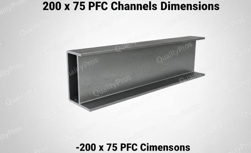
Based on international standards (EN 10279, AS/NZS 3679), the 200 x 75 PFC has these core specifications:
| Parameter | Value |
|---|---|
| Depth (w) | 200 mm |
| Flange Width (F) | 75 mm |
| Web Thickness (WT) | 6.0 mm |
| Flange Thickness (FT) | 12.5 mm |
| Weight | 23.4 kg/m |
| Root Radius (r) | 12 mm |

| Parameter | Value | Tolerance |
|---|---|---|
| Depth (h) | 200 mm | ±3 mm |
| Flange Width (b) | 75 mm | ±2 mm |
| Web Thickness (tw) | 6.0 mm | ±0.5 mm |
| Flange Thickness (tf) | 12.5 mm | ±0.7 mm |
| Weight | 23.4 kg/m | ±5% |
| Root Radius (r) | 12 mm | ±1 mm |
*Note: Weights vary slightly (e.g., 22.9 kg/m in some regions) due to manufacturing processes.*
🏗️ Top Applications: Where 200 x 75 PFC Excels
- Lintels & Door/Window Supports
- The 75mm parallel flanges provide a flush surface for brickwork or cladding, while the 200mm depth resists deflection under masonry loads. Often welded to a base plate for cavity walls .
- Mezzanine Floor Joists
- Lightweight (23.4 kg/m) yet strong, these channels support dynamic loads in warehouses. Pair with Universal Beams (UB) for hybrid frameworks.
- Roof Trusses & Bracing
- High torsional rigidity makes them ideal for wind bracing in portal frames. The straight flanges simplify bolting to gusset plates.
- Trailer/Vehicle Chassis
- Compatible with S355JR steel grade (yield strength: 355 MPa), offering fatigue resistance for mobile equipment.
⚠️ Critical Design Considerations
- Material Grades:
- S355JR (common in EU/UK): Impact-tested for -20°C environments.
- AS/NZS 3679.1: Australian standards prioritize weldability.
- Connection Efficiency:
Parallel flanges eliminate tapered washers, speeding up assembly vs. UPN channels. - Load Limits:
- Vertical Load Capacity: ~12 kN/m (over 3m span).
- Torsional Stress: Avoid unsupported spans >4m to prevent buckling.
🔧 Fabrication Tips & Best Practices
- Drilling & Welding:
- Flanges tolerate up to 14mm bolt holes without reinforcement.
- Preheat to 150°C when welding to S690 high-strength steel.
- Corrosion Protection:
- Hot-dip galvanizing (recommended for outdoor use) adds ~0.1mm thickness – account for this in tight tolerances.
- Pairing for Cavity Walls:
Bolt two PFCs back-to-back with 100mm spacers for dual-leaf support.
💡 Why Choose 200 x 75 Over Alternatives?
| Profile | Flange Type | Key Advantage | 200 x 75 PFC Edge |
|---|---|---|---|
| UPN (e.g., U200) | Tapered | Higher bending resistance | Easier connections |
| C-Channel (AISC) | Tapered | Lower cost | Better torsion control |
| MC-Channel | Wider parallel | Heavy-load capacity | Lighter weight |
Parallel flanges mean no conical washers, 30% faster assembly, and uniform stress distribution.
🌟 Industry Insight
*“We use 200 x 75 PFCs in 80% of our mezzanine projects. Their depth-to-weight ratio cuts steel costs by 15% vs. deeper sections.”*
– Project Manager, Industrial Construction Firm
📌 Key Takeaway
The 200 x 75 PFC blends versatility with structural efficiency. Its dimensions optimize load distribution for mid-span applications, while parallel flanges future-proof designs for fast modifications. Always specify:
- Steel grade (e.g., S355JR vs. GR 300),
- Finish (galvanized/primer),
- Hole patterns (web/flange)